
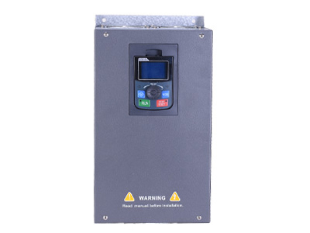

Q13 series frequency converter is a multi-functional, high-performance vector inverter, using the most professional motor drive technology, safe and reliable, optional XSP05 panel (potentiometer) and XSP10 panel (LCD), more convenient operation; Suitable for electronic equipment, packaging, printing, machine tools, hardware, engineering and other occasions.
Single phase 220V 0.75-5.5KW Three-phase 380V 0.75-200KW
|
Projects |
Specifications |
||
|
Basic control function |
Maximum frequency |
Vector Control: 0 ~ 500Hz ZV/F control: 0 ~ 500Hz
|
|
|
Carrier Frequency |
0.5kHz~16kHz The carrier frequency can be adjusted automatically according to the load characteristics. |
||
|
Input frequency resolution
|
Digital setting: 0.01 Hz analog setting: MAX frequency × 0.025%
|
||
|
Control Mode |
Open-loop vector control (no PG) Closed-loop vector control (with PG) V/f control |
||
|
Starting Torque |
H: 0.5 Hz/150% (no PG) ; 0hz/180% (PG) ; L: 0.5 Hz/100%
|
||
|
Speed range |
1:100(no PG) |
1:1000 (There is PG) |
|
|
Speed stability accuracy |
±0.2% (no PG) |
±0.02% (There is PG) |
|
|
Torque control accuracy |
±5% (There is PG) |
||
|
Overload capacity |
Model H: 150% rated current 60s; 180% rated current 3s. Model L: 120% rated current 60s; 150% rated current 3s.
|
||
|
Torque Boost |
Automatic torque improvement, manual torque improvement of 0.1% ~ 30.0% |
||
|
V/f curve |
Three types: straight line; multi-point; n-power V/F curve (1.2 power, 1.4 power, 1.6 power, 1.8 power, 2 power)
|
||
|
V/F separation |
2 ways: full separation, half separation |
||
|
Acceleration and deceleration curves |
Linear or s-curve acceleration and deceleration mode. Four kinds of acceleration and deceleration time, acceleration and deceleration time range 0.0 ~ 6500.0 s
|
||
|
DC brake |
DC brake frequency: 0.00 hz-maximum frequency Braking time: 0.0 S ~ 36.0 s Braking current: 0.0% ~ 100.0% |
||
|
Point Control |
Tap frequency range: 0.00 hz-50.00 Hz. The acceleration and deceleration time is 0.0 s ~ 6500.0 s. |
||
|
Simple PLC, multi-speed operation |
Through the built-in PLC or control terminal to achieve up to 16 segments of speed operation |
||
|
Projects |
Specifications |
||
|
|
Built-in PID |
The process control closed-loop control system can be conveniently realized |
|
|
Automatic voltage regulation (AVR) |
When the network voltage changes, can automatically maintain the output voltage constant |
||
|
Overvoltage and overcurrent stall control |
Automatic limit of current and voltage during operation to prevent frequent overcurrent and overvoltage trip |
||
|
Fast current limiting function |
Minimizes overcurrent failure and protects the converter from normal operation |
||
|
Torque limitation and control
|
“Excavator” features, the operation of torque automatic limit to prevent frequent overcurrent trip; closed-loop vector mode can achieve torque control |
||
|
Personalized features |
Superior performance |
Asynchronous motor and synchronous motor are controlled by high performance current vector control technology |
|
|
All the time |
The reduction of the voltage compensated by the load feedback energy can keep the inverter running for a short time during the transient power failure |
||
|
Fast current limiting |
Avoid frequency converter frequent over-current fault |
||
|
Timing control |
Timing control function: set time range 0.0 min-6000.0 min |
||
|
Means of communication |
Support: Rs -485 |
||
|
Protective function |
On-motor short-circuit detection, input and output protection, over-current protection, over-voltage protection, under-voltage protection, over-heat protection, overload protection |
||
|
Run |
Run the instruction channel |
The Operation Panel is given, the control terminal is given and the serial communication port is given. You can switch between them in a number of ways
|
|
|
Frequency source |
Multiple frequency sources: digital set, analog voltage set, analog current set, pulse set, serial port set. You can switch between them in a number of ways |
||
|
Auxiliary frequency source |
10 auxiliary frequency sources. The auxiliary frequency fine-tuning and frequency synthesis can be flexibly realized |
||
|
Input Terminal |
Standard: 5 digital input terminals, 1 for high-speed pulse input up to 100kHz 2 analog input terminals, 1 for 0-10V voltage input only, 1 supports 0-10V voltage input or 4-20mA current input
|
||
|
Output Terminal |
1 high-speed pulse output terminal (optional open-circuit collector type) , support 0-100kHz square wave signal output 1 digital output terminal 1 relay output terminal 2 analog output terminal, support 0-20mA current output or 0-10V voltage output
|
||

|
Frequency converter model |
Quota output power (KW) |
Input Current (A)
|
Output Current(A) |
ADAPTOR motor(KW) |
|
|
Single-phase input power supply: 220V (-15% ~ + 15%) , 50/60Hz |
|||||
|
Q13-2S0007H |
0.75 |
10.5 |
4.5 |
0.75 |
|
|
Q13-2S0015H |
1.5 |
14.5 |
7.0 |
1.5 |
|
|
Q13-2S0022H |
2.2 |
21.4 |
10.0 |
2.2 |
|
|
Q13-2S0037H |
3.7 |
35.9 |
17.0 |
3.7 |
|
|
Q13-2S0055H |
5.5 |
42 |
25 |
5.5 |
|
|
Three-phase input power supply: 380V (-15% ~ + 15%) , 50/60Hz |
||||
|
Q13-4T0007H |
0.75 |
3.5 |
2.5 |
0.75 |
|
Q13-4T0015H |
1.5 |
6.2 |
4.0 |
1.5 |
|
Q13-4T0022H |
2.2 |
9.2 |
5.5 |
2.2 |
|
Q13-4T0040H |
4.0 |
14.9 |
9 |
4.0 |
|
Q13-4T0055H |
5.5 |
21.5 |
13 |
5.5 |
|
Q13-4T0075H |
7.5 |
28.9 |
18 |
7.5 |
|
Q13-4T0110H |
11 |
39.0 |
24 |
11 |
|
Q13-4T0150H |
15 |
50.3 |
33 |
15 |
|
Q13-4T0180H |
18 |
60.0 |
38 |
18 |
|
Q13-4T0220H |
22 |
69.3 |
45 |
22 |
|
Q13-4T0300H |
30 |
86 |
60 |
30 |
|
Q13-4T0370H |
37 |
104 |
75 |
37 |
|
Q13-4T0450H |
45 |
124 |
91 |
45 |
|
Q13-4T0550H |
55 |
150 |
112 |
55 |
|
Q13-4T0750H |
75 |
160 |
150 |
75 |
|
Q13-4T0900H |
90 |
180 |
175 |
90 |
|
Q13-4T1100H |
110 |
196 |
210 |
110 |
|
Q13-4T1320H |
132 |
232 |
250 |
132 |
|
Q13-4T1600H |
160 |
282 |
300 |
160 |
|
Q13-4T2000H |
200 |
352 |
415 |
200 |
|
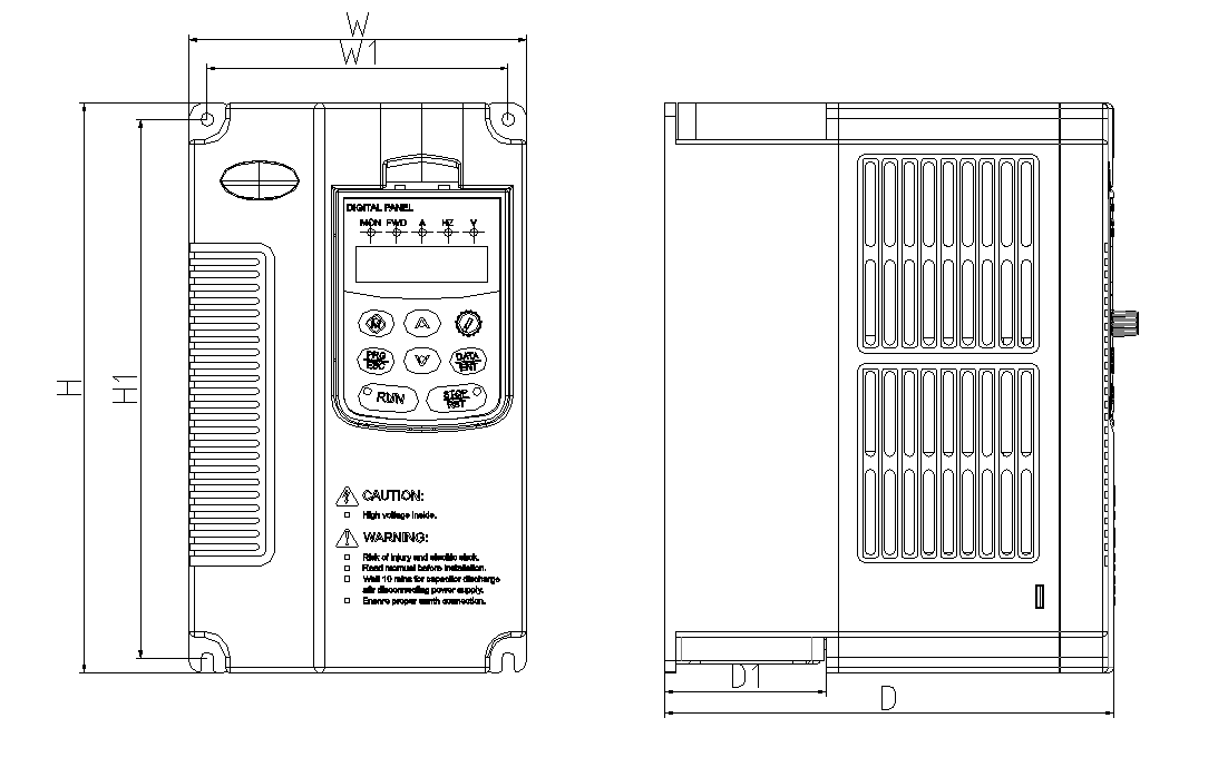
Voltage level |
Type of aircraft |
Frequency converter model |
Shape and mounting dimensions (mm) |
||||||
|
W |
H |
D |
W1 |
H1 |
D1 |
Mounting holes |
|||
|
220V |
A |
Q13-2S0007H |
118 |
185 |
145 |
105 |
173 |
45 |
5 |
|
Q13-2S0015H |
|||||||||
|
Q13-2S0022H |
|||||||||
|
B |
Q13-2S0037H |
130 |
220 |
181 |
116 |
208 |
60 |
5 |
|
|
Q13-2S0055H |
|||||||||
|
380V |
A |
Q13-4T0007H |
118 |
185 |
145 |
105 |
173 |
45 |
5 |
|
Q13-4T0015H |
|||||||||
|
Q13-4T0022H |
|||||||||
|
C |
Q13-4T0040H |
118 |
185 |
181 |
105 |
173 |
60 |
5 |
|
|
B |
Q13-4T0055H |
130 |
220 |
181 |
116 |
208 |
60 |
5 |
|
|
Q13-4T0075H |
|||||||||
|
D |
Q13-4T0110H |
208 |
322 |
192 |
190 |
306 |
112 |
7 |
|
|
Q13-4T0150H |
|||||||||
|
Q13-4T0180H |
|||||||||
|
E |
Q07-4T0220H |
220 |
380 |
190 |
185 |
404 |
138 |
7 |
|
|
Q07-4T0300H |
|||||||||
|
F |
Q07-4T0370H |
256 |
430 |
202 |
196 |
450 |
153 |
7 |
|
|
Q07-4T0450H |
|||||||||
|
G |
Q07-4T0550H |
320 |
575 |
233 |
220 |
553 |
101 |
10 |
|
|
Q07-4T0750H |
|||||||||
|
H |
Q07-4T0900H |
404 |
615 |
249 |
270 |
590 |
110 |
10 |
|
|
Q07-4T1100H |
|||||||||
|
I |
Q07-4T1320H |
466 |
745 |
325 |
343 |
715 |
184 |
12 |
|
|
Q07-4T1600H |
|||||||||
|
J |
Q07-4T2000H |
540 |
890 |
377 |
370 |
856 |
205 |
14 |
|
Keypad outside pull tray hole size:110mm*74mm